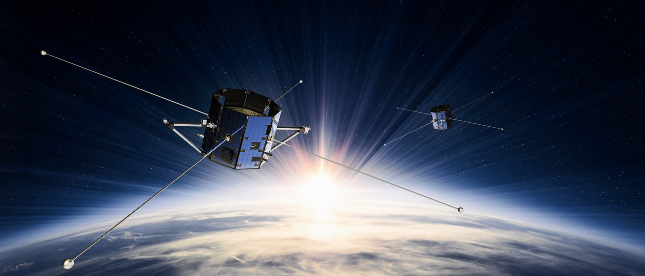
Banner image credit: Millennium Space Systems
The EFI instruments measure the ambient electric field associated with plasma flow and electromagnetic fluctuations in the low-altitude cusp.
How EFI works
EFI allows us to estimate the primary components of the electric field. This is accomplished by measuring the differences in electric potential between two spatially separated pairs of electrodes (or antennas), at frequencies from DC to nearly 10 MHz. Field-aligned current systems and the lowest frequency electric field variations quasi-statically and dynamically couple energy and momentum from the magnetopause reconnection site into the low-altitude cusp region. The higher frequency variations (up to 1 kHz and from 100 kHz up to 10 MHz) can couple those larger-scale energy sources into local ionospheric heating and exhibit natural resonance frequencies in the plasma that provide accurate estimates of local plasma density.
Technical details
Technical details
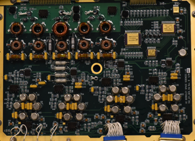
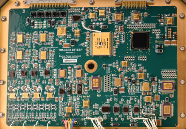
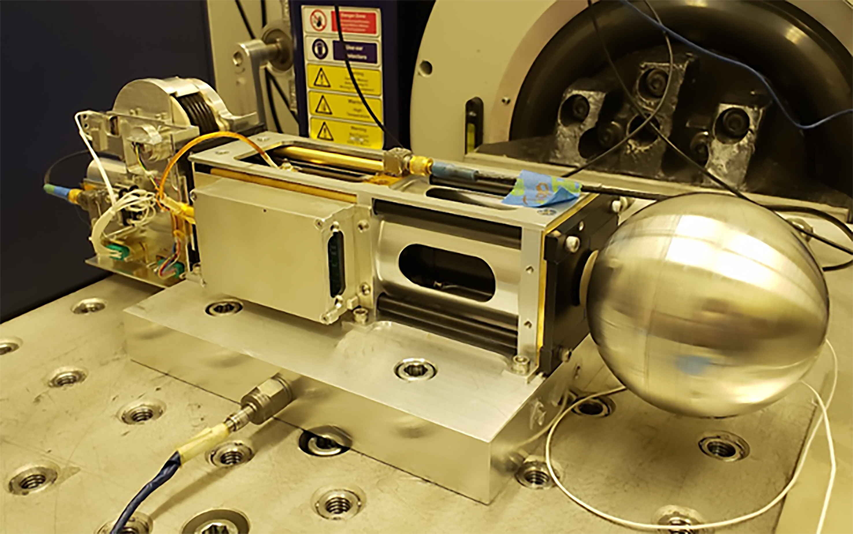
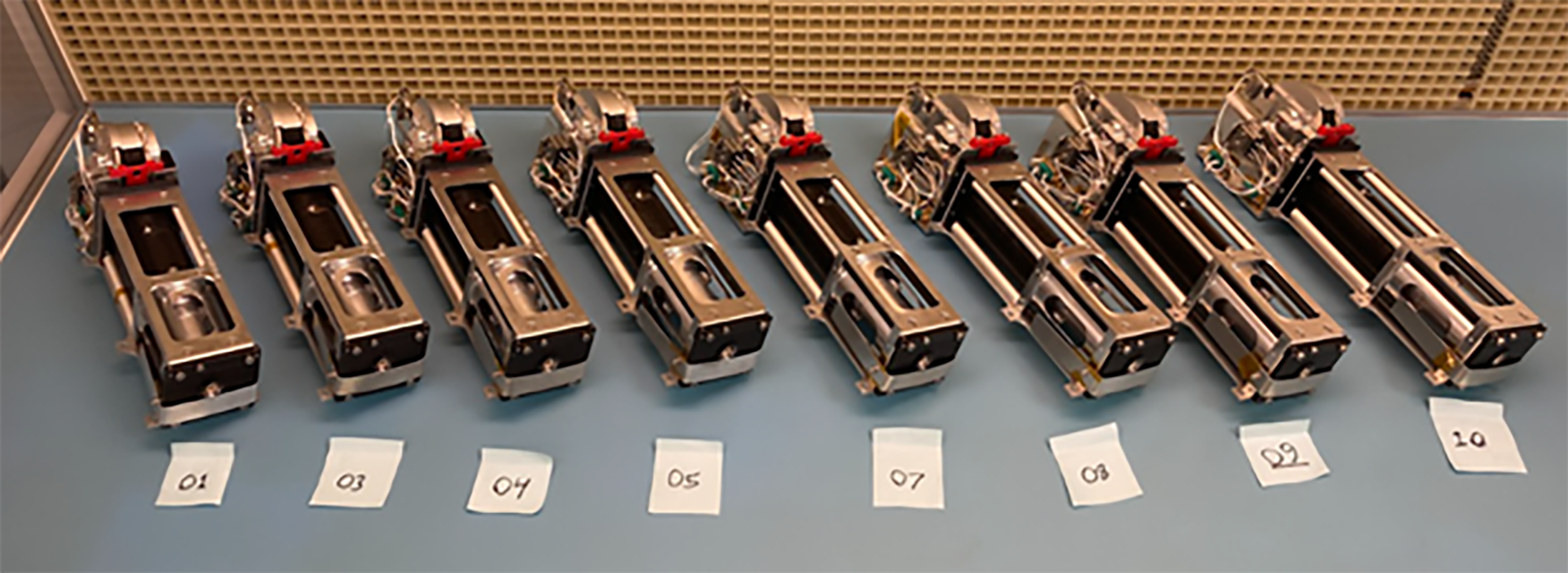
Each EFI consists of an orthogonal pair of double-probe electric field sensors with sphere-to-sphere spacing of 7 meters deployed via 3 meter stacer booms in the spacecraft spin plane for the DC/low frequency (LF) sections, and two of the four stacer boom surfaces for the high frequency (HF) measurements (two 3 meter monopoles, separated by 1 meter at the root). Each 8 cm diameter spherical sensor contains a LF Preamp, and may be current-biased to optimize DC and AC performance on orbit as controlled via the Boom Electronics Board (BEB) in the Main Electronics Box (MEB). The Electric Signal Processing (ESP) board provides analog and digital signal processing of the measured voltages of each sensor relative to SC ground as well as the AC magnetic field signals measured by the MSC instrument. The ESP packetizes the EFI and MSC data and transfers those data to the CDPU for compression, storage, and eventual forwarding to the SC form transmission to the ground. The ESP also provides the commanding interface to it and the BEB from the CDPU.
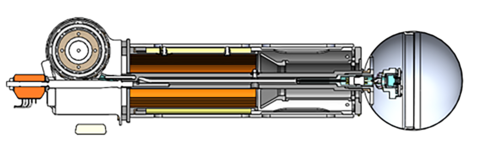
For scale, the sphere has an 8 cm outside diameter, and the total stowed length of the boom unit is less than 40 cm. The 300 cm long helical spring that forms the stacer lies coiled in a less than 10-cm long can, providing a 30-to-1 stowed to deployed length ratio. The stacer boom is held in place prior to deployment on orbit via a shape-memory-alloy (SMA) actuated FrangiBolt fastener, and deploys slowly at a rate set by a centrifugal breaking mechanism that provides tension in the custom multi-conductor cable spooled on the reel at the rear of the unit.
| PARAMETER | PERFORMANCE |
|---|---|
| Accuracy | ± 1 mV/m |
| Sampling Rates | EDC and VDC at 128 samples/s in ROI EDC and VDC at 8 samples/s in BOR Snapshots of EAC at 2048 samples/s in ROI and BOR 16,384-sample EHF snapshots every 16s at 20Msamples/s |
| Data Products | Eperp, spacecraft floating potential, ne. |
| Dynamic Ranges | Sensor Channels (VDC) ≈ ±40 V E-field (EDC) ≈ ±1 V/m |