Banner image credit: Millennium Space Systems
The ACE instruments allow the team to precisely determine the edges of the funnel-shaped magnetospheric cusp region that connects the Earth’s ionosphere (part of the upper atmosphere) to the distant magnetopause.


How ACE works
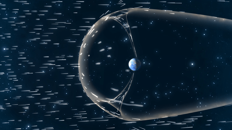
At the cusps, plasma that has been shocked by the solar wind has direct access to Earth's ionosphere. These special regions - the cusps - therefore represent conduits for solar wind material and energy to interact directly with the terrestrial environment.
Electrons follow tightly wound helical paths along magnetic field lines. When the orbit takes the two TRACERS spacecraft into the cusp, the ACE instruments measure the distribution of electrons and resolve the fluxes of electrons as a function of energy and direction. This provides a complete picture of the properties of both downward-going (precipitating) and upward-going electrons. Therefore, the ACE measurements of precipitating electrons allows for precise determination of the extent of the funnel-shaped magnetospheric cusp.
Technical Details
Technical details
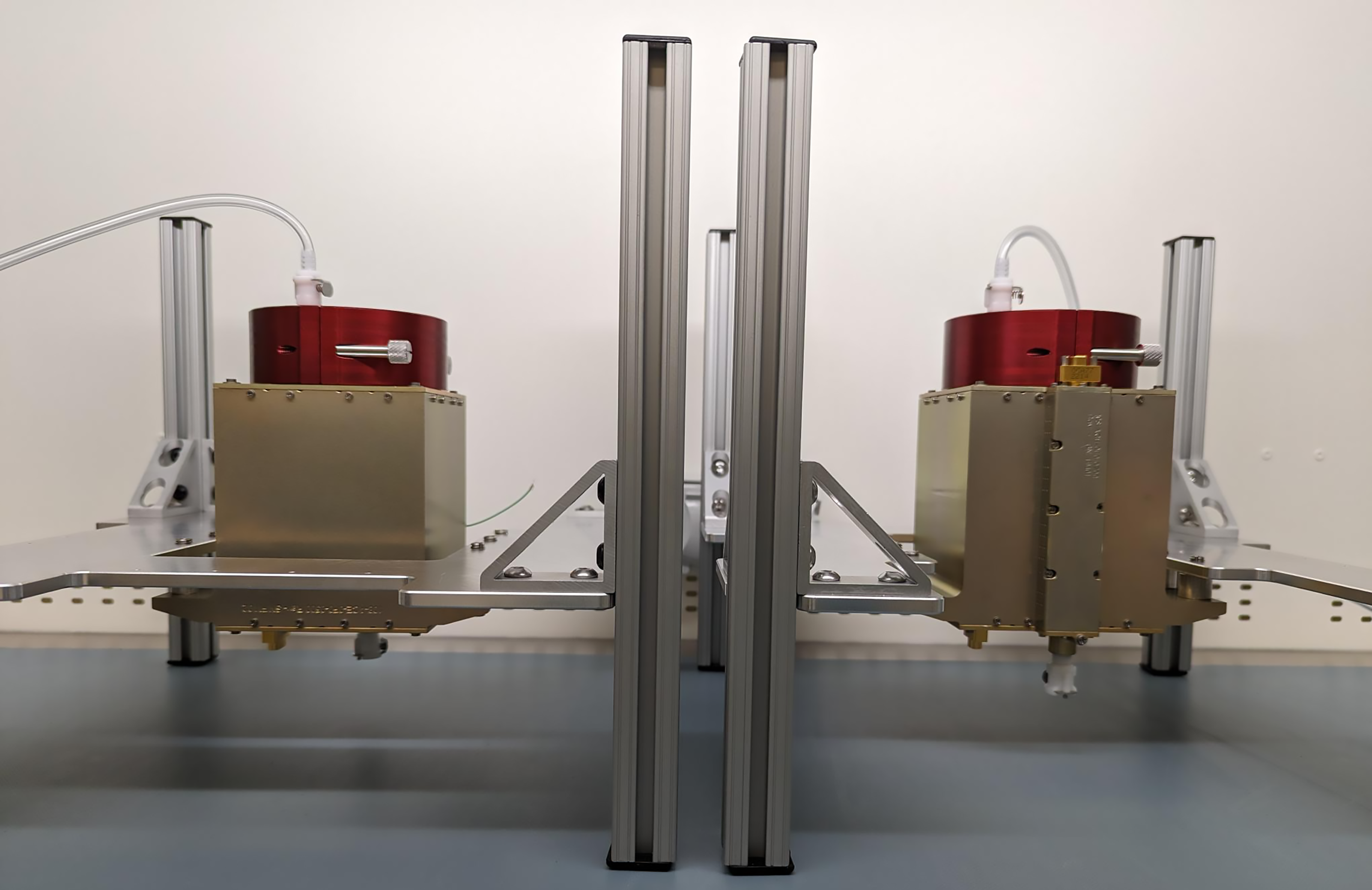
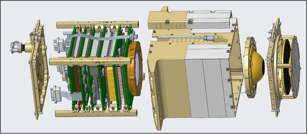
Each ACE instrument consists of a single integrated sensor and electronics box. The sensor consists of a top-hat electrostatic analyzer, with a grounded outer hemisphere and top cap concentric with an inner hemisphere biased with positive high voltages to select electrons in a series of energy ranges. Electrons in each selected energy range follow great circle arcs through the narrow gap between the hemispheres, and strike the top face of a chevron-pair microchannel plate (MCP) detector. With high efficiency, incident electrons generate secondary electron cascades, resulting in output pulses of 1-2 million electrons. The charge pulses from the MCP land upon 21 metallized anodes, each of which registers a 10° range of entrance azimuthal angles. Charge-sensitive preamplifiers convert these charge pulses to digital logic signals, which are then accumulated in counters in an FPGA for each anode and energy step, producing a matrix of counts as a function of energy and angle. A high-voltage power supply generates the high voltages for the input and output faces of the MCP detector stack, as well as the swept inner hemisphere voltage that selects electrons by energy. A low-voltage power supply produces the regulated low voltages utilized by the instrument from the unregulated power from the spacecraft, routed through the Main Electronics Box (MEB) to ACE. ACE accepts commands from and sends telemetry to the MEB through a serial interface.
| Parameter | performance |
|---|---|
|
Temporal Resolution per Sample (50 energy steps, 21 angles) |
0.05 s |
| Energy Range | 20 – 11,500 eV |
| Energy Resolution | 18.7% ΔE/E FWHM |
| Angular Coverage per Sample | 210° x 7° |
| Angular Coverage per Spacecraft Spin | Full 4π sr |
| Angular Resolution | 10° x 7° |
| Sensitivity (Differential Energy Flux) | 105– 1010 eV/[cm2 s sr eV] |
How we got to ACE
ACE has direct heritage from multiple sounding rocket experiments into the cusp, the most recent two being TRICE-2 and ACES-II. Though it is largely the same instrument, appropriate updates have been made for the TRACERS mission.
The design of ACE is based on a standard top-hat electrostatic analyzer design. The ACE sensor incorporates simple digital and low-voltage power supply (LVPS) functionality.